CATIA V5 Professional — Industry-Ready Mechanical Design & Product Develpment Program
Categories: Mechanical Design & Engineering
About Course
 Course Description
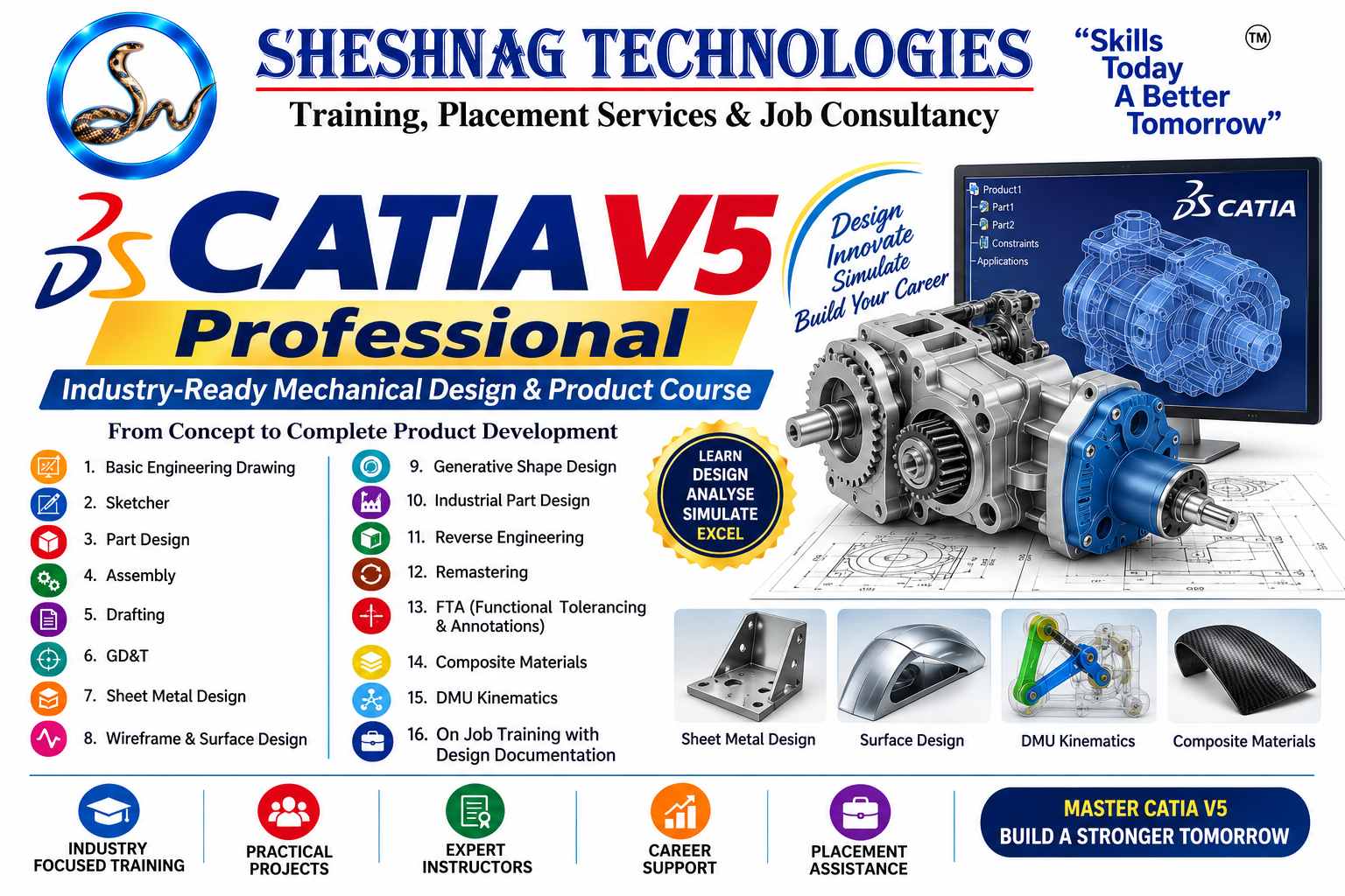
CATIA V5 Professional – Industry-Ready Mechanical Design & Product Development Program is a comprehensive professional training program designed for mechanical engineering students, graduates, CAD designers, design engineers and professionals who want to develop advanced skills in mechanical product design, 3D CAD modelling, engineering documentation and industrial design workflows.
The program covers the complete CATIA V5 design journey, beginning with Engineering Drawing, Sketcher, Part Design, Assembly and Drafting, and progressing into specialized professional areas such as GD&T, Sheet Metal Design, Wireframe & Surface Design, Generative Shape Design, Industrial Part Design, Reverse Engineering, Remastering, FTA, Composite Materials and DMU Kinematics.
Learners will work on practical design exercises and industry-oriented projects covering 3D modelling, assemblies, engineering drawings, tolerancing, complex surfaces, sheet-metal components, mechanisms and design documentation. DMU Kinematics, for example, is specifically used for mechanism creation and motion simulation in CATIA V5.
The program concludes with On-Job-Style Training with Design Documentation, helping learners understand how professional CAD work can be organized from design requirements through modelling, assembly, documentation, review and final design delivery.
by — Bhalachandra Pawar, Design engineer
What Will You Learn?
- By completing this program, learners will develop professional CATIA V5 and mechanical design skills in:
- Engineering & Mechanical Design
- Engineering drawing fundamentals and drawing interpretation
- Design standards, dimensions, tolerances and fits
- Design intent and feature planning
- Professional mechanical design workflows
- CATIA V5 Core
- CATIA V5 interface and workbench environment
- Sketcher and advanced sketch constraints
- Part Design and complex 3D modelling
- Assembly Design and assembly constraints
- Drafting and engineering documentation
- Advanced Engineering Design
- GD&T and tolerance application
- Sheet Metal Design
- Wireframe Design
- Surface Design
- Generative Shape Design (GSD)
- Industrial Part Design
- Reverse Engineering
- Remastering and CAD data reconstruction workflows
- FTA – Functional Tolerancing & Annotation
- Composite Materials fundamentals
- DMU Kinematics and mechanism simulation
- Professional Design Workflow
- Design modification and engineering change workflows
- Assembly review
- Design documentation
- Manufacturing drawing preparation
- Annotation and tolerancing
- BOM/documentation fundamentals
- Design review and correction
- Practical project development
- Portfolio-oriented CAD projects
- On-Job-Style Training
- GSD and advanced surfacing are particularly relevant to complex geometry, while sheet-metal training commonly includes walls, bends, flanges, stamping features and flat-pattern outputs.
- By -- Bhalachandra Pawar, Design Engineer by profession
Course Content
SECTION 1 — Basic Engineering Drawing & Mechanical Design Fundamentals
-
Introduction to Engineering Drawing
-
Importance of engineering drawings in mechanical design
-
Drawing instruments and CAD-based drafting concepts
-
Drawing standards and conventions
-
Types of lines and their applications
-
Lettering, numbering and drawing presentation
-
Geometrical constructions
-
Scales and proportional drawing
-
Orthographic projection
-
First-angle and third-angle projection
-
Isometric and pictorial views
-
Sectional views
-
Full, half, offset and broken sections
-
Dimensioning techniques
-
Linear, angular and radial dimensions
-
Limits, fits and tolerances
-
Surface-finish symbols
-
Welding and machining symbols
-
Reading and interpreting mechanical drawings
-
Introduction to design intent
-
Practical
-
Mechanical component drawing interpretation
-
Orthographic-to-isometric exercise
-
Sectional-view exercise
-
Complete mechanical drawing practice
-
Project
-
Mechanical Component Drawing & Interpretation Project
SECTION 2 — CATIA V5 Sketcher
-
Sketcher workbench introduction
-
Sketch support and sketch orientation
-
Creating a new sketch
-
Sketcher interface and toolbars
-
Profile creation
-
Lines, polylines and rectangles
-
Circles and arcs
-
Slots and obrounds
-
Spline and complex curves
-
Construction geometry
-
Projected 3D elements
-
Intersecting 3D elements
-
Geometrical constraints
-
Dimensional constraints
-
Horizontal/vertical constraints
-
Coincidence and tangency
-
Parallelism and perpendicularity
-
Symmetry and concentricity
-
Fully constrained sketches
-
Under-constrained sketch analysis
-
Sketch modification and troubleshooting
-
Design intent
-
Sketch patterns
-
Advanced profile creation
-
Practical
-
Fully constrained mechanical profiles
-
Shaft profile
-
Flange profile
-
Bracket profile
-
Complex industrial profile
-
Project
-
Fully Constrained Mechanical Component Sketch
SECTION 3 — CATIA V5 Part Design
Part Design is the primary CATIA environment for creating 3D solid parts from sketches and features.
-
Part Design workbench
-
Creating a CATPart
-
Bodies and PartBody
-
Sketch-based features
-
Pad
-
Pocket
-
Shaft
-
Groove
-
Hole
-
Rib
-
Slot
-
Multi-section solid
-
Thick Surface
-
Draft
-
Fillet
-
Chamfer
-
Shell
-
Patterns
-
Rectangular pattern
-
Circular pattern
-
User-defined patterns
-
Boolean operations
-
Remove/Add/Assemble
-
Multi-body design
-
Body management
-
Datum planes and axes
-
Design tables fundamentals
-
Feature editing
-
Parent-child relationships
-
Design intent
-
Complex component modelling
-
Model validation and measurement
-
Practical Projects
-
Mechanical bracket
-
Bearing housing
-
Flange
-
Shaft component
-
Mounting component
-
Complex mechanical component
-
Power Copy Method
-
Final Project
-
Complete Industrial Mechanical Part
SECTION 4 — CATIA V5 Assembly Design
Assembly Design is used to position components and establish mechanical relationships between them.
-
Assembly Design introduction
-
Creating a CATProduct
-
Product structure
-
Component insertion
-
Existing component insertion
-
New component creation
-
Fixing components
-
Assembly constraints
-
Coincidence
-
Contact
-
Offset
-
Angle constraints
-
Component manipulation
-
Snap and positioning
-
Sub-assemblies
-
Bottom-up assembly
-
Top-down assembl
-
Assembly design methodology
-
Interference checking
-
Clash analysis fundamentals
-
Exploded views
-
Assembly specification tree
-
Component replacement
-
Design modifications
-
Assembly documentation
-
Bill of Materials fundamentals
-
Assembly review
-
Practical Projects
-
Bearing assembly
-
Gear assembly
-
Coupling assembly
-
Mechanical clamp
-
Shaft and bearing assembly
-
Final Project
SECTION 5 — CATIA V5 Drafting
CATIA Drafting is used to generate 2D engineering drawings from parts and assemblies.
-
Drafting workbench introduction
-
Creating drawing sheets
-
Sheet standards
-
Drawing views
-
Front view
-
Projection views
-
Section views
-
Auxiliary views
-
Detail views
-
Isometric views
-
View positioning
-
View generation
-
View modification
-
Dimensioning
-
Automatic dimensions
-
Reference dimensions
-
Tolerance display
-
Center lines and center marks
-
Welding symbols
-
Surface-finish symbols
-
Text and annotations
-
Datum representation
-
Drawing frames and title blocks
-
Drawing templates
-
Parts lists
-
Balloons
-
Assembly drawings
-
Drawing revision concepts
-
Printing and PDF output
-
Professional drawing documentation
-
Project
-
Complete Manufacturing Drawing Package
SECTION 6 — GD&T: Geometric Dimensioning & Tolerancing
-
Introduction to GD&T
-
Purpose of GD&T
-
GD&T terminology
-
Datum concepts
-
Datum features
-
Feature control frames
-
Form tolerances
-
Straightness
-
Flatness
-
Circularity
-
Cylindricity
-
Orientation tolerances
-
Parallelism
-
Perpendicularity
-
Angularity
-
Location tolerances
-
Position
-
Concentricity
-
Symmetry
-
Profile tolerances
-
Circular runout
-
Total runout
-
MMC
-
LMC
-
RFS
-
Bonus tolerance
-
Datum reference frames
-
Reading GD&T drawings
-
Applying GD&T to mechanical components
-
CATIA-based tolerance representation
-
Practical
-
Complete GD&T Mechanical Component Drawing
SECTION 7 — CATIA V5 Sheet Metal Design
-
Sheet Metal Design introduction
-
Sheet metal parameters
-
Sheet thickness
-
Bend radius
-
Bend allowance fundamentals
-
Sheet metal wall creation
-
Wall on edge
-
Flanges
-
Bend creation
-
Bend relief
-
Corner treatment
-
Chamfers
-
Cutouts
-
Holes
-
Stamping features
-
Sheet metal transformations
-
Unfolding
-
Folding
-
Flat pattern generation
-
Bend representation
-
Sheet metal design rules
-
Sheet metal drafting
-
Manufacturing documentation
-
Projects
-
Final Project
SECTION 8 — Wireframe & Surface Design
Wireframe and Surface Design is used for creating curves and surface geometry, particularly where solid modelling alone is not sufficient.
-
Wireframe and Surface Design introduction
-
Geometrical sets
-
Points
-
Lines
-
Planes
-
Circles
-
Splines
-
Helix
-
Projection
-
Intersection
-
Offset
-
Connect Curve
-
Boundary
-
Surface extrusion
-
Revolved surfaces
-
Sweep
-
Multi-section surfaces
-
Fill
-
Join
-
Split
-
Trim
-
Extrapolation
-
Healing surfaces
-
Surface continuity
-
Surface analysis
-
Surface-to-solid conversion
-
Surface-based product modelling
-
Project
SECTION 9 — Generative Shape Design (GSD)
GSD is particularly suited to complex surface geometry; CATIA documentation also includes advanced GSD functions such as geometrical-set management, Power Copies, sectioning, patterning and surface/volume workflows.
CATIA Documentation
-
GSD workbench introduction
-
Geometrical sets
-
Ordered geometrical sets
-
Advanced wireframe creation
-
Advanced curves
-
Spline creation
-
Projection
-
Intersection
-
Offset
-
Boundary
-
Connect Curve
-
Extrapolation
-
Sweep
-
Multi-section surface
-
Fill
-
Blend
-
Healing
-
Join
-
Split
-
Trim
-
Surface continuity
-
Tangency and curvature continuity
-
Surface analysis
-
Dynamic sectioning
-
Power Copies
-
Surface-based solid creation
-
Complex product surfaces
-
Advanced surface modification
-
Projects
-
Final Project
SECTION 10 — Industrial Part Design
-
Introduction to industrial product design
-
Industrial component development
-
Design intent
-
Feature planning
-
Complex Part Design
-
Multi-body modelling
-
Advanced dress-up features
-
Complex fillets
-
Draft analysis concepts
-
Thickness concepts
-
Ribs and bosses
-
Mounting features
-
Fastener locations
-
Plastic component fundamentals
-
Industrial housings
-
Product enclosure design
-
Manufacturing considerations
-
Design modification
-
Design review
-
Industrial design project workflow
-
Projects
-
Final Project
SECTION 11 — Reverse Engineering
-
Introduction to reverse engineering
-
Reverse engineering workflow
-
Physical component to CAD workflow
-
Measurement concepts
-
Reference geometry
-
Imported geometry
-
Point-cloud fundamentals
-
Scan data concepts
-
Curve extraction
-
Surface reconstruction
-
Section-based modelling
-
Wireframe reconstruction
-
Surface reconstruction
-
Solid reconstruction
-
Design-intent reconstruction
-
Comparing original and reconstructed geometry
-
Modification of reconstructed models
-
Manufacturing-ready reconstruction
-
Documentation of reverse-engineered components
-
Practical
-
Final Project
SECTION 12 — Remastering & CAD Data Reconstruction
For your course, I recommend teaching Remastering as a professional workflow for rebuilding, cleaning, restructuring and improving existing CAD data.
-
Introduction to CAD remastering
-
Understanding legacy CAD data
-
Imported model analysis
-
Data quality assessment
-
Geometry cleanup
-
Healing imported geometry
-
Removing unwanted features
-
Rebuilding design features
-
Recreating design intent
-
Reconstructing sketches
-
Rebuilding Part Design features
-
Recreating feature trees
-
Surface remastering
-
Solid remastering
-
Converting imported geometry into editable models
-
Model simplification
-
Design modification
-
Standardization of CAD data
-
File organization
-
Validation of remastered models
-
Project
SECTION 13 — FTA: Functional Tolerancing & Annotations
CATIA's FTA environment supports 3D tolerances and annotations directly on parts/products, including datums, datum targets, reference frames, dimensions and geometric tolerances.
CATIA Documentation +1
-
Introduction to FTA
-
Functional tolerancing concepts
-
3D annotation methodology
-
Annotation standards
-
Creating annotation views
-
Creating annotation text
-
Creating dimensions
-
Datum creation
-
Datum targets
-
Datum reference frames
-
Feature control frames
-
Geometrical tolerances
-
Form tolerances
-
Orientation tolerances
-
Location tolerances
-
Profile tolerances
-
Runout tolerances
-
Tolerance modifiers
-
Semantic annotations
-
Non-semantic annotations
-
Annotation properties
-
Annotation filtering
-
Tolerancing Advisor
-
Tolerance application to holes
-
Tolerance application to grooves
-
Pattern tolerancing
-
3D annotation management
-
Manufacturing-oriented annotation workflow
-
CATIA’s FTA documentation specifically covers standards, semantic support, geometrical tolerancing, datum principles and annotation management.
-
CATIA Documentation +1
-
Project
SECTION 14 — Composite Materials
-
Introduction to composite materials
-
Composite material fundamentals
-
Applications of composites
-
Fibre and matrix concepts
-
Unidirectional composites
-
Woven materials
-
Laminate concepts
-
Ply orientation
-
Material properties
-
Ply thickness
-
Laminate stacking sequence
-
Composite design terminology
-
Composite part modelling concepts
-
Composite structure representation
-
Ply definition concepts
-
Symmetric and balanced laminates
-
Manufacturing considerations
-
Composite design documentation
-
Inspection considerations
-
Composite product development workflow
-
Practical
-
Project
SECTION 15 — DMU Kinematics
DMU Kinematics is used for creating and simulating mechanical movement through kinematic relationships between assembly components.
-
Introduction to DMU Kinematics
-
Digital mock-up concepts
-
Kinematic mechanism fundamentals
-
Creating mechanisms
-
Fixed components
-
Joints
-
Revolute joint
-
Prismatic joint
-
Cylindrical joint
-
Planar joint
-
Spherical joint
-
Universal joint
-
Gear-related mechanisms
-
Screw mechanisms
-
Kinematic constraints
-
Degrees of freedom
-
Command creation
-
Simulation
-
Mechanism analysis
-
Motion limits
-
Collision/interference considerations
-
Mechanism modification
-
Animation
-
Mechanism documentation
-
Projects
-
Final Project
SECTION 16 — On-Job-Style Training with Design Documentation
This should be the capstone section where students combine the individual CATIA workbenches into a professional workflow.
-
Module 1 — Understanding a Design Requirement
-
Module 2 — Design Planning
-
Module 3 — Professional Part Development
-
Module 4 — Assembly Development
-
Module 5 — Engineering Documentation
-
Module 6 — Design Changes
-
Module 7 — Design Review
-
Module 8 — Professional Project
-
Final Capstone Project
-
Final project presentation
Student Ratings & Reviews

No Review Yet